ISSN 1884-0760
GRACE TECHNICAL REPORTS
Proceedings of the 13th Overture Workshop
Fuyuki Ishikawa and Peter Gorm Larsen
GRACE-TR 2015–06
June 2015
CENTER FOR GLOBAL RESEARCH IN
Proceedings of the 13th Overture Workshop
23 June, 2015
http://overturetool.org/workshops/13th-Overture-Workshop.html
The 13th edition of the “Overture” series of workshops on the Vienna Development Method (VDM), its associated tools and applications, was held in conjunction with the FM 2015 symposiumi. This workshop aims to provide a forum for discussing and advancing the state of the art in formal modelling and analysis using VDM and its family of associated formalisms including extensions for distributed and real-time systems.
Although VDM is one of the oldest formal methods to have enjoyed a level of industry use, it nevertheless has a lively and youthful research community, which has grown up around the development of the Overture open tools platformii. On top of the Overture platform the Crescendoiii and Symphonyiv tools from respectively the DESTECSv and COMPASSvi projects, as well as the new development that will take place in the new INTO-CPS projectvii (see http://into-cps.au.dk/). The platform provides a vehicle for activity in modelling and analysis technology including static analysis, interpreters, test generation and execution support and model checking. The growth of this community has been greatly assisted by the Overture workshop series.
The 13th workshop reflected the breadth and depth of work in VDM. The invited talk by Taro Kurita (Sony) reports the evolution of its VDM usage for their development of Mobile Felica IC chips, focusing on the aspect of readability, i.e., formal models as documents.
Research contributions included topics about essential challenges in concurrency and real-time aspects. Connection and integration with a variety of directions are also covered, including requirements and stakeholders, theorem provers, and test-driven development. Last but not least, application and visionary papers are provided to promote discussions for next directions of the Overture community.
We would like to thank the authors for the interesting contributions and the PC members and reviewers for their advices to make this workshop valuable and successful.
i The 20th International Symposium on Formal Methods (FM 2015): http://fm2015.ifi.uio.no/
ii Overture Tool: http://overturetool.org/ iii Crescendo Tool: http://crescendotool.org/ iv Symphony IDE: http://symphonytool.org/ v DESTECS Project: http://destecs.org/
vi COMPASS Project: http://www.compass-research.eu/ vii INTO-CPS Project: http://into-cps.au.dk/
Table of Contents
Advance in VDM Application to Development of Mobile FeliCa IC Chip Firmware -
Toward Readable VDM Specification for Reliable System and Good Relationships ...1
Taro Kurita
JODTool on the Overture Tool to manage formal requirement dictionaries …………..3
Yoichi Omori, Keijiro Araki and Peter Gorm Larsen
VDM Animation for a Wider Range of Stakeholders ………18
Tomohiro Oda, Yasuhiro Yamamoto, Kumiyo Nakakoji, Keijiro Araki and Peter
Gorm LarsenIntegrating the PVSio-web modelling and prototyping environment with Overture 33
Paolo Masci, Luis Diogo Couto, Peter Gorm Larsen and Paul Curzon
Extending the Overture code generator towards Isabelle syntax ……….48
Luis Diogo Couto and Peter W. V. Tran-Jorgensen
Code Generation of VDM++ Concurrency ………..60
Georgios Kanakis, Peter Gorm Larsen and Peter W. V. Tran-Jorgensen
Generating Java RMI code for the distributed aspects of VDM-RT models …………75
Miran Hasanagic, Peter Gorm Larsen and Peter W. V. Tran-Jorgensen
Improving Time Estimates in VDM-RT Models ………90
Morten Larsen, Peter Wurtz Vinter Tran-Jorgensen and Peter Gorm Larsen
Case Studies on Combination of VDM and Test-Driven Approaches: Application, Model
Finding and Refinement ………..104
Fuyuki Ishikawa
Pacemaker Parameter Tuning using Crescendo ……….116
Carl Gamble, Martin Mansfield, John Fitzgerald and Peter Gorm Larsen
Program Committee
Keijro Araki, Kyushu University, Japan
Nick Battle, Fujitsu, UK
John S Fitzgerald, Newcastle University, UK
Tomohiro Oda, Software Research Associates, Inc., Japan
Jose Nuno Oliveira, Minho University, Portugal
Nico Plat, West Consulting, Netherlands
Volker Stolz, Oslo University, Norway
Advance in VDM Application to Development of
Mobile FeliCa IC Chip Firmware
- Toward Readable VDM Specification for
Reliable System and Good Relationships
(Extended Abstract for Invited Talk)
Taro Kurita
Sony Corporation, [email protected]
“FeliCa” is a contactless IC card technology developed by the Sony Corpo-ration and is widely used in Japan. In particular, Mobile FeliCa IC chips are embedded in over 250 million mobile phones. Their applications, including elec-tronic money, train tickets, identifications, door keys, and so on, form an essential foundation for business and daily activities in Japan.
Given the significance of the system, VDM was applied to the development of the second generation of its firmware [1, 2]. It successfully contributed to resolution of problems in the early phases, such as vagueness in the specification. This talk discusses the succeeding development of the third generation started in 2007. This development involved many features, such as enhancement of the encryption mechanisms and adaptation of the global standard of Near Field Communication (NFC). The implementation code was three times the LOC of the second-generation. The usage of VDM was improved especially for maintain-ability and understandmaintain-ability, i.e., to facilitate the iterative process and commu-nications among involved teams.
In the third generation, the VDM specification was considered as the sole specification document that worked as the reference for various development activities. In other words, it was not wrapped or hidden by natural-language documents, and was referred to by more engineers including those from external partner companies. This change eliminated costly and error-prone maintenance for two versions of the documents in the natural language and VDM. On the other hand, this change made readability of the VDM specification indispensable, though it had been found significant in the previous development.
Table 1.Comparison of the Second and Third Generations Generation C Implementation VDM Specification
[LOC] [LOC]
Second 40,876 39,315
Third 126,944 55,400
(LOC excludes comments and blank lines)
Generation Deficiencies by Deficiencies by Productivity Debug density description comprehension [LOC/Man-month] [errors/kLOC]
Second 2% 16.3% 1,000 11
Third 0% 10.9% 1,000 11
There were other improvements including the following ones.
– Use of the Japanese in variable and method names that considerably de-creased the amount of comments on the VDM specification.
– Management of multiple products in the specification and testing.
– Systematic methods for generating test cases from the VDM specification. Table 1 shows comparison of the second and third generations. Increase of the specification lines was moderate by declarative description, even with the large increase of the implementation lines. Deficiencies caused by the description and the comprehension were both decreased, while the productivity and debug density were kept to a similar level.
Our experience demonstrated how readability of the VDM specification can be improved. We believe the readability is one of the key factors that support not only construction of reliable systems but also effective and harmonious re-lationships in the involved teams.
Acknowledgments
We would like to thank Professor Peter Gorm Larsen of Aarhus University, Shin Sahara of Hosei University and Hiroshi Sako of Designers’ Den Corporation for their great assistance in the application of VDM.
References
1. Kurita, T., Chiba, M., Nakatsugawa, Y.: Application of a formal specification lan-guage in the development of the “Mobile FeliCa” IC chip firmware for embedding in mobile phone. In: The 15th International Symposium on Formal Methods (FM 2008). pp. 425–429 (2008)
2. Kurita, T., Nakatsugawa, Y.: The application of VDM to the industrial develop-ment of firmware for a smart card IC chip. International Journal of Software and Informatics 3(2-3), pp. 343–355 (2009)
JODTool on the Overture Tool to manage formal
requirement dictionaries
Yoichi Omori1, Keijiro Araki1, and Peter Gorm Larsen2 1 Department of Advanced Information Technology,
Graduate school of Information Science and Electric Engineering, Kyushu University,
{yomori@ait,araki@csce}.kyushu-u.ac.jp 2 Department of Engineering
Aarhus University [email protected]
Abstract. The traceability between a software requirement specification in nat-ural language and its corresponding formal specification plays an important role in development and maintenance of software. JODTool is a tool to support the activities of formal specifiers to bridge from a pre-formal specification to a for-mal specification. It manages a forfor-mal requirement dictionary, which is a set of tuples of a key-phrase and its definition to keep bi-directional traceability. The tool provides mainly three functionalities; 1) Key phrase marker 2) Dictionary editor, and 3) Format converter, on the Overture tool to map key phrases to VDM-SL/VDM++ specifications. We propose an evolutionary process of a round-trip between pre-formal specification and formal specification with the tool, and illus-trate it with a small case study. The tool is seamlessly integrated into the Overture environment, and it lists concrete ambiguities in the SRS to be resolved, and sup-ports prioritised modeling in VDM specification.
Keywords: Requirement Specification, Requirement Traceability, Overture tool, Formal Requirement Dictionary, VDM modeling
1
Introduction
A software requirement specification (SRS) expressed using natural language is the starting point of software development in most project. It is clear that tenders, con-tracts, or projects of a certain scale demand an explicit SRS. Natural language usually contains, however, contradictions and ambiguities, therefore careful reviews and repeat-ing rewrites are required to achieve an agreement among stakeholders.
engineers thorough the software life cycle, though a formal method is adopted in the software development.
Traceability is an important feature to use a natural language and a formal method together, in order to check whether the formal specification is covering the SRS in nat-ural language. The advantage of requirement dictionary in the specification phase is well known, however it is often omitted because of its construction cost[2]. We had proposed a dictionary management tool named JODTool for formal requirements dic-tionary which manages the map between key phrases in SRS and their definition by formal language [16]. A formal requirement dictionary is a set of tuples made of a key phrase as a small semantic chunk and its formal semantic definition, which represents bi-directional translation between them.
JODTool extends application of lightweight formal method [11] to requirement specification process. The concept of lightweight formal method is utilisation of ver-ification tools instead of rigid mathematical proves, which are typically constructed semi-automatically. The aims to introduce the formal requirement dictionary are;
– The semantic gap of natural language and a program would be buried by a formal specification.
– Verification by tools in small units to improve reusability and accuracy of corre-spondence.
– The mapping between a semantic chunk in SRS and its formal definition must be surjective.
A phrase is not a grammatical meaning here, but the minimum unit which makes it distinctly different from other phrases in the specification. For example, an “apple” is the minimum chunk in a system which distinguishes an “apple” and other obstacles, but if a target system distinguishes a “red apple” and a “green apple”, the minimum chunk in the specification must be “red apple” and “green apple.” In short, grammatical knowledge is insufficient to find key phrases and they should be identified by formal specifiers considering the purpose of the system and domain knowledge.
Formal specifier cannot construct the proper formal model all at once. They will write and verify a formal specification from important parts considering the priority of requirements. When the verification is successful, they extend the model to incorporate other requirements. Formal specifiers develop the specification by repeating this.
This paper proceeds by providing the related work that this work is based on in Sec-tion 2. Afterwards the noSec-tion of a formal requirement dicSec-tionary and its management possibilities on top of the Overture tool is explained in Section 3. Then the application procedure of an evolutionary formal modeling process with the tool is presented in Sec-tion 4. The case study of applicaSec-tion to a parking deck system is reported in SecSec-tion 5, and some analyses over the result is performed in Section 6. Finally, we summarize our results in Section 7.
2
Related Work
Tools to manage the mapping between requirements in natural language and program fragments are available as commercial products. Some tools to manage mapping
tween requirements in natural language and detailed design are available as commer-cial products, such as Rational DOORS [18], Mingle [19] and Caliber [17]. They store arbitrary mapping based on the traceability matrix which maps relations among listed specifications, design in some diagram or documents. However, it is difficult to assure that all requirements are turned into specification without any kinds of contradictions in large-scale software development.
The limits of natural language software specifications were pointed out, and the in-vestigations to what extend formal descriptions can improve has been investigated [15]. Traditional application of formal methods assumes that the conversion into formal spec-ification from requirements in natural language is one-way. On the contrary, our tool provides an easy way to support round trip development.
The concept of the domain requirements dictionary is close to the concept of the data dictionary used in the structured analysis method [3]. The data dictionary in structured analysis describes the structure of the data used in data flow diagrams, and it must contain definitions of all the data used.
Formal requirement dictionary is an extension of the requirement dictionary which is proposed in real time structured analysis [8] It is an extension of the requirements dictionary to contain a formal definition for each phrase of not only a data structure but functions or modules. The extension points are:
– Entry is not limited to a word but a key phrase. – Semantics is defined by a formal language.
– The dictionary can be converted into a formal model.
3
Dictionary runs with Overture tool
3.1 Dictionary Management Tool
We had developed a formal requirement dictionary management tool which is named JODTool to assist formal specifiers. Current version of the tool supports the guideline to construct a model with VDM-SL [4] or VDM++ [13].
Key phrases are stored into a dictionary and the user can here complement formal information in the dictionary. It is implemented as an Eclipse plug-in whose perspective has a SRS Editor, a Formal Requirement Dictionary Editor, and an Entry Editor. We successfully integrated JODTool into the Overture tool and propose an evolutionary process to develop a formal and pre-formal specification over the environment.
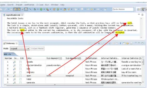
Fig.1 shows interface of the tool. The tool provides 3 main functionalities:
Key phrase Registrar: The SRS Editor enables marking of all key phrases in natural language documents which are entry phrases of the formal requirement dictionary. As a result, the visibility of key phrases in the documents may be much improved for the specifiers as shown in Fig. 1.
The mouse selected regions are added to the specified dictionary as an entry phrase by one click or a short-cut command. Registration is performed easily on an arbi-trary phrase.
The SRS Editor is able to handle plain text file, HTML files and a limited form of a Microsoft Excel file.
Fig. 1.The GUI of the JODTool
Entry Editor: The dictionary data can be edited through the entry editor view. The view provides basic editing operations such as copy-paste, search, sorting, for the entry, order of the entry, and dictionaries in the project, respectively.
An entry consists of a natural language part and a formal language part. The natural language part consists of a key phrase which is represented as a sequence of char-acters and an informal definition in a natural language. The tuple of key phrase and its part of speech gives key value in the formal requirement dictionary. The entry allows regular expressions of the entry phrases.
A key phrase can contains sub-key phrases which are compositions of the concept, synonyms, or paraphrases. It may also have conjunctions of the key phrase from the grammatical view. The dictionary provides a small structure to arrange “unstable” concepts in a natural language.
The formal language part consists of a section and an atomic portion of formal semantic definition. The entry keeps a bi-directional relation between descriptions in a natural language and a formal language.
Model Conversion: The tool supports translation from the formal definitions in the dictionary into a formal specification which can be checked by verification tool such as the Overture tool [12]3or VDMTools [5]4.
3See http.//overturetool.org for details. 4See http://www.vdmtools.jp/en/ for details.
The current version of JODTool supports both VDM-SL and VDM++, so the for-mal specifier can use one of these languages to give a forfor-mal definition of the key phrases.
3.2 Relations among dictionaries
JODTool is equipped with functionality to support requirement analysis and enhanced traceability including handling of multiple dictionaries. Therefore, a dictionary is reusable not only the case of two specification sharing the same domain but also they can have overlapped parts.
Fig. 2.Dictionary reuse
In the case where a term is defined differently in two directories it is possible to switch the dictionary as shown in Fig. 3.
Fig. 3.Dictionary switching
Combined key phrase and sub-key phrases may share the same definition, and in such cases equivalent terms, or synonyms can be combined. The dictionary format is extended so that plural keywords can be registered into one entry. If you cannot correct the SRS directly, the dictionary can be used to resolve such ambiguities.
Variations of main key phrases are also stored in the same entry. Variations are supposed to be conjugations of verbs or declension of adjectives. The document marker check the main key phrase, sub key phrases, and all the conjugated forms as the same part.
The tool can simultaneously open multiple dictionaries corresponding to different domains, respectively. The dictionary is stored in an XML form and has a header and subsequent entries. The dictionary header has following fields:
Domain name: Domain name is an identifier of a domain and it is not limited to a problem domain, but can be arbitrary text strings.
Organization: Organization is an identifier of a project or an organization. A spec-ification of the target depends on not only on its domain but its users and their application environment.
Input language: An input language is the descriptive language of non formal infor-mation in an entry of the dictionary. You can set multiple input languages in a dictionary.
Output language An output language is the descriptive language of the formal defini-tion in an entry of the dicdefini-tionary.
A specification process is not a one-way transition from an informal SRS to a formal model. The key phrases and sub key phrases in the dictionary are highlighted in the SRS editor on the fly as shown in Fig. 4. It becomes easier to provide feedback with corrections to the SRS, if the formal model is modified.
Fig. 4.Track back to SRS
3.3 Integration with the Overture tool
JODTool has been successfully integrated into the Overture tool, as shown in Fig. 1. We reorganized the namespace in the plug-in implementation, provided coexistence of the specification file and the dictionary generated by JODTool with projects of the Overture tool, delegation of VDM-SL and VDM ++ editor, etc.
The Overture tool is most popular and standard VDM integrated development en-vironment built on Eclipse, which includes new features of the VDM languages. The integration enables formal specifiers to analyze by extracting key phrases of an SRS in natural language, to construct VDM specifications based on the set of key phrases, and to generate VDM source files from the dictionary. Overture can the perform syntax and type checking, and the formal specification and the pre-formal specification can be modified in a unified way. They can seamlessly continue the repetition to evolve the formal specification. It is possible to validate the specification by animation of explicit specifications [14] or by using proof obligations [1].
Defects of the specification found in the above process can be fed back to the SRS by identification using the reverse mapping of the dictionary. Though VDM modeling without the dictionary can point out defects in SRS, the formal requirement dictionary clarify the defects as concrete technical problems of the specification, rather than inabil-ity of the specifier. It demonstrates which part of SRS contains what type of problem because of the mathematical background of the formal method.
4
Repetitive Evolution of formal specification
A formal specifier cannot normally construct the proper formal model in one step be-cause abstraction from a prioritised point of view and good understanding of the target system are necessary to apply a formal method properly. However, it might take time to understand the full functionality and the priorities among them in the target system. Specifiers have to communicate with the domain experts and other stakeholders, and begin the formal specification from most important part of requirements.
Fig. 5.Suppression of output
In the construction of a formal specification, the specifier describes and verify a partial formal model. JODTool supports such evolutionary modeling process. VDM originally provides some notations for transitional modeling, such as the “is not
yet specified” keyword. JODTool can control the output elements outside the model as shown in Fig. 5. Thus, the specifier do not hesitate to cut and error over the constructing model. Essential changes of requirements must act upon the model itself. When the verification is successful for the partial formal model, they can extend the model to incorporate other requirements.
We propose that it is possible to develop a formal specification the following proce-dure in this tool environment:
1. Extract all key phrases in the SRS.
2. Choose the high-priority elements and give them a formal definition. 3. Generate a partial model and verify it.
4. If any defects are discovered fed it back to the SRS.
5. Otherwise no problem is discovered, and the next high-priority elements can be selected to be incorporated in the model and go to step 3.
6. Finish the repetition if all key phrases are given a formal definition
Formal specifiers develop the specification by repeating this cycle. If eventually all key phrases are incorporated in the formal model, it can be said that reflection of whole the SRS into the model was completed. This does not mean the model is complete or the model is best one, but the specifier can explain objectively that the model contains all indispensable elements about the target system. It is practically important in application formal methods that clear indication of the termination condition of modeling process.
5
Case study
5.1 The Parking Deck System
We adopted a park deck problem as a case study of our method. A parking deck is a stacked garage, thus it has multiple parking space in it. The assignment is used in a course of George Mason University [7], as shown in Fig.6.
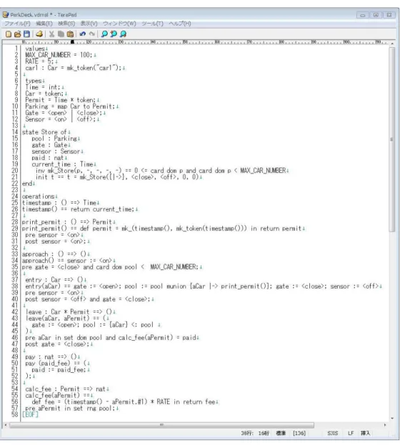
The VDM-SL model was composed of 84 lines excluding comments. No errors were discovered in the VDM model when it was checked by the Overture tool but that was expected. The main part of the specification is shown in Fig. 7.
The key concept of this model is that “Parking” is defined as a map from a car to a permit. The relation is quite simple and will not change through this whole system. Consequently a state component is defined of this type. However, this requires intuition of the specifier, because this definition stands on an abstraction of car and parking lot. From the viewpoint of enter/exit management of Park Deck, a car is a simple object and a permit is a tuple of an ID and its entry time.
All verbs in this example are corresponding to the operations. Thus, every move of this system changes its state, as they commonly do in embedded systems. The VDM-SL model was composed from the definitions of key phrases in the dictionary.
5.2 Application of evolutionary process
We applied the procedure in Section 4.
A parking deck system manages an entry/exit gate, which opens to let a vehicle (i.e., car) into or out of the deck and closes when the car has passed through. A driver must push a button to print a parking permit. When the driver takes the parking permit, the system raises the gate. The system lowers the gate after the vehicle has passed through. A permit id and time of entry is printed on the parking permit, and is also encoded on the permit’s bar code.
When the vehicle leaves the parking deck, the driver inserts the parking permit into a bar code reader, which scans the bar code, and then transmits the bar code to the parking system. The parking system calculates a fee that is based on the number of hours that have elapsed since the vehicle entered the parking deck, and displays the fee to the operator and driver. The driver must pay the operator with cash or check. The operator accepts the payment, and if necessary returns change to the driver. Then, the operator enters a command to raise the gate to allow the vehicle to leave the parking deck. You may assume that the system has the following external devices at the entry gate: a sensor to detect the presence of a car, a parking ticket printer to print the parking permit, an actuator to open and close the gate, and a sensor to detect that the car has departed. You may assume that the system has the following external devices at the exit gate: a bar code scanner to read the permit bar code id, a display to show the parking fee to the operator and driver, an actuator to open and close the gate, and a sensor to detect that the car has departed.
Fig. 6.Park Deck Problem
1. Extract all key phrases in the SRS.
We have extracted the important key phrases from the SRS using JODTool. Accord-ing to the statistics of the tool, 8 noun phrase, 7 verb phrases, and 3 state variables were selected. There were many conjunctions of verbs and synonyms. For example, we identified “parking deck”, “deck”, “parking system”, “the system” denoted the same concept.
2. Choose the high-priority elements and give them formal definition.
We adopted a top-down approach to model the informal description of the system. Only the “ParkingDeck” module was generated in the first iteration. Then, the no-tion of “Parking” and its related state components and operano-tions to the model was added in the second cycle. Afterwards other elements were added too and the VDM model was completed.
3. Generate a partial model and verify it.
You can control the model output by the ability shown in Fig. 5. The Overture tool runs syntax and type checking process automatically, so the specifier can fix faults in the formal model in a short amount of time.
4. If any defects are discovered fed these fixes back to the SRS.
We found some synonyms in the SRS so that they are stored in one entry, and put some key phrases together and built some structures at conceptual level. For example, key phrases “open”, “close”, “raise”, “lower” were put into “gate” and its states.
We also added a number of concepts that seemed to be missing. They came from the level of abstraction, thus most of them were type definitions which were distinct from the static state component.
Fig. 7.Formal model using VDM-SL
If you do not wish to rewrite the SRS for some reason, the specifier can manage the semantics of each phrase manually.
5. Otherwise no problem is detected in the model and the next level of priorities can be added to the model and go to step 3.
Repeat the cycle until the model achieve the mutable goal of verification or vali-dation. Here, verification is the process to confirm elimination of inconsistency in each model and validation is the process to confirm elimination of inconsistency among the models of different models.
6. Finish the repetition if all key phrases are given formal definition.
We eventually obtained 7 noun phrase, 5 verb phrases, 3 state components, and 9 others were picked up. Others includes type definitions, constants, and test data.
5.3 Alternate dictionaries
Pick up the billing of the example in sec. 5.1 as an example of refinement.
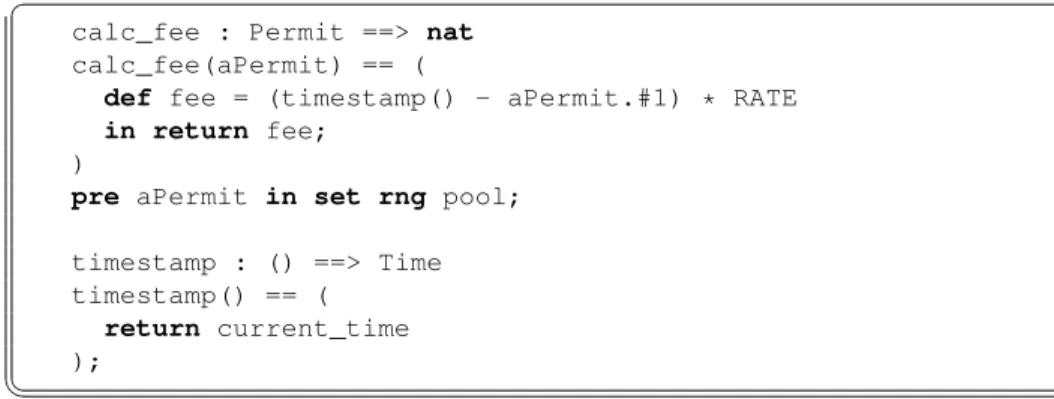
The entry of the formal domain dictionary is “calculates a fee”, and its formal defi-nition is Fig. 8.
✞
calc_fee : Permit ==> nat calc_fee(aPermit) == (
def fee = (timestamp() - aPermit.#1) * RATE in return fee;
)
pre aPermit in set rng pool;
timestamp : () ==> Time timestamp() == (
return current_time );
✡✝ ✆
Fig. 8.Formal Billing Operation
Actual calculation partval feeis cut out for this comparison. The problem is that the meaning of the sentence in natural language
a fee is calculated based on the number of elapsed hours
is ambiguous, so that various interpretations are allowed. For example, the fee calcula-tion as Fig. 9,
Ifval feeis defined as that, it is not obvious whether this satisfies the original specification. If formal definition of the part is Fig. 8, then Fig. 9 satisfies Fig. 8, because concrete specification is left to the latter phase. Fig. 10 satisfies Fig. 9 in the same way.
✞
val_fee: Time ==> nat val_fee (time) ==
return time * RATE;
✡✝ ✆
Fig. 9.Refined Formal Billing Operation(1)
✞
val_fee: Time ==> nat val_fee (time) ==
if time <2 then return 1 else return 2 * (time -2) + 2;
✡✝ ✆
Fig. 10.Refined Formal Billing Operation(2)
On the other hand, if formal definition of the part is Fig. 9, it can be proved that Fig. 10 does not satisfies Fig. 9, because any condition cannot satisfy Fig. 9 in Fig. 10. In this case, the specifier interpreted the part in natural language as the fee is proportional to the elapsed time.
6
Discussion
6.1 Bi-directional Mapping of Specification and Model
There have been many investigations about whether formal methods are useful for solv-ing this kind of problems, and it is well-known as a way to reach improvement and assurance of software quality [6, 9, 21, 20].
The main difficulty of practicing formal methods is that mathematical knowledge and intuition is required, whereas native natural language can be used by most stake-holders without extra training. We propose the developing method using both specifi-cations in a natural language and in a formal language. The stakeholders who know the formal method can understand the exact semantics, and those who are unacquainted with the mathematics can refer to the natural language description which semantics is captured by the formal method.
The duality of the formal domain dictionary helps co-existence of readability and rigidness of the specification.
Fig. 11 shows some roles of stakeholders.
Customer: The customer presents requirements to the specifier in natural language form.
Specifier: The specifier turns the requirements into a formal specification.
Developer: The developer refers to the formal specification and implements a corre-sponding program.
Formal specifications are desirable to avoid misunderstanding among stakeholders, but it depends on the familiarity about formal methods of each member.
Fig. 11.Supposed Development Process
6.2 Evolutionary development
In the software development using formal methods, some steps of refinement are ap-plied to the specification and finally this leads to executable code. (Horizontal direction from the left to the right in Fig. 12) If specification n obeys specification m, the relation is called refinement and it expresses with a⊑sign.
Another view is a formal model can be obtained from a corresponding specifica-tion. (Vertical direction from the upper to the lower in Fig. 12) The formal requirement dictionary gives the mapping between a specification and a model. If the dictionary changes, the model needs to be changed accordingly. Different dictionaries express dif-ferent viewpoints of the target. Between the formal models sharing the same formal language, a.k.a sharing the same formal method, can be proved whether they have the refinement relation5.
Fig. 12.Relation among specification and models
A formal requirement dictionary gives a mapping from the specification to the model, thus conditions for existence of such inverse mapping is that mapping is bidi-rectional. Therefore specifier can notice the necessity to keep consistency when either side is changed. Mapping must be surjective by definition, i.e. a formal definition can be given for any semantic chunk in natural language.
If mapping from the specification to the model is not injective, it is trivially not monotonic, where the same definition is given for multiple semantic chunks. To avoid
5
When they are in different languages but sharing the same mathematical theory, this kind of relation can be apparently defined, but it is out of scope in this paper.
this case, a representative should be chosen from the group of chunks with the same formal definition, and use it in the inverse mapping.
The consistency of the specification in natural language and the specification in for-mal model and refinement relation between specifications is defined under the condition of bidirectional mapping from the specification to the model.
7
Conclusion and Future work
This paper introduces the formal requirement dictionary and its integration with the Overture tool. JODTool manages formal requirement dictionary and which runs with the Overture tool to verify and validate VDM models. The dictionary ensure traceabil-ity between SRS in natural language and its corresponding formal model. It supports specifier’s task and relations among formal requirement dictionaries.
– In a case study, we found 18 key phrases in the SRS in the first cycle. But, there should be abstract types or constants and finally we had 24 entry in the formal requirement dictionary. This means that there is a difference between a sufficient model and a good model.
– The Overture tool provides quick syntax and type check, therefore the formal spec-ification in VDM quickly achieve a stable model. If you need advanced verspec-ification or validation such as animation, the specifier can do that in the unified environment. – A formal model with the tool is a good start point to begin refinement. Because formal requirement dictionary can ensure that all key phrases in the SRS are incor-porated in the corresponding formal specification.
It is future work to perform examination on larger examples and to confirm reusabil-ity, considering the generic relation between natural language description and the formal specification.
Acknowledgment
Thanks to Dr. Hassan Gomaa for the publication of a Park Deck Problem as an example specification. Construction of the tool is supported by Mr. Yasuharu Yoshimura and others in Kyushu Business Corporation. This work was partially supported by MEXT Grant-in-Aid for Scientific Research(S) HBG4220001.
References
1. Aichernig, B.K., Larsen, P.G.: A Proof Obligation Generator for VDM-SL. In: Fitzgerald, J.S., Jones, C.B., Lucas, P. (eds.) FME’97: Industrial Applications and Strengthened Foun-dations of Formal Methods (Proc. 4th Intl. Symposium of Formal Methods Europe, Graz, Austria, September 1997). Lecture Notes in Computer Science, vol. 1313, pp. 338–357. Springer-Verlag (September 1997), iSBN 3-540-63533-5
2. Daneva, M.: Erp requirements engineering practice: Lessons learned. IEEE Software 21(2), 26–33 (2004)
3. Demarco, T.: Structured Analysis and System Specification. Yordon Press (1981)
4. Fitzgerald, J., Larsen, P.G.: Modelling Systems: Practical Tools and Techniques for Software Developmen. Cambridge University Press, 2 edn. (2009)
5. Fitzgerald, J., Larsen, P.G., Sahara, S.: VDMTools: Advances in Support for Formal Model-ing in VDM. ACM Sigplan Notices 43(2), 3–11 (February 2008)
6. Gerhart, S., Craigen, D., Ralston, T.: Experience with formal methods in critical systems. IEEE Software 11(1), 21–28 (1994)
7. Gomma, H.: Course assignments for software modeling and design. http://mason.gmu.edu/ hgomaa/assignments.html
8. Hatley, D.J., Pirbhai, I.A.: Strategies for Real-Time System Specification. Dorset House (1988)
9. Hinchey, M.G., Bowen, J.P. (eds.): Applications of Formal Methods. Prentice Hall (1995) 10. Jones, C.B.: Software development based on formal methods. In: Proceedings of the CRAI
Workshop on Software Factories and Ada. LNCS, vol. 275, pp. 153–172. Springer-Verlag (1987)
11. Jones, C.B., Jackson, D., Wing, J.: Formal methods light. IEEE Computer 29, 20–22 (1996) 12. Larsen, P.G., Battle, N., Ferreira, M., Fitzgerald, J., Lausdahl, K., Verhoef, M.: The Overture Initiative – Integrating Tools for VDM. SIGSOFT Softw. Eng. Notes 35(1), 1–6 (January 2010), http://doi.acm.org/10.1145/1668862.1668864
13. Larsen, P.G., Mukherjee, P., Plat, N., Verhoef, M., Fitzgerald, J.: Validated Designs For Object-oriented Systems. Springer (2005)
14. Lausdahl, K., Larsen, P.G., Battle, N.: A Deterministic Interpreter Simulating A Distributed real time system using VDM. In: Qin, S., Qiu, Z. (eds.) Proceedings of the 13th interna-tional conference on Formal methods and software engineering. Lecture Notes in Com-puter Science, vol. 6991, pp. 179–194. Springer-Verlag, Berlin, Heidelberg (October 2011), http://dl.acm.org/citation.cfm?id=2075089.2075107, ISBN 978-3-642-24558-9
15. Meyer, B.: On formalism in specifications. IEEE Software 2(1), 6–26 (1985)
16. Omori, Y., Araki, K.: Tool support for domain analysis of the software specification in natural language. In: Proceedings of the IEEE TENCON 2010. pp. T7–3.3(CD–ROM) (2010) 17. Borland: Caliber. http://www.borland.com/products/caliber/
18. IBM: Rational DOORS. http://www-03.ibm.com/software/products/en/ratidoor
19. Thought Works: Mingle. http://www.thoughtworks.com/products/mingle-agile-project-management
20. Stefania Gnesi, T.M.: Formal Methods for Industrial Critical Systems: A Survey of Applica-tions. Wiley-IEEE Computer Society (2012)
21. Woodcock, J., Larsen, P.G., Bicarregui, J., Fitzgerald, J.: Formal Methods: Practice and Ex-perience. ACM Computing Surveys 41(4), 1–36 (October 2009)
VDM Animation for a Wider Range of Stakeholders
Tomohiro Oda1
, Yasuhiro Yamamoto2
, Kumiyo Nakakoji1,3, Keijiro Araki4, and Peter Gorm Larsen5
1
Software Research Associates, Inc. ([email protected]) 2
University of Tokyo ([email protected]) 3
Kyoto University ([email protected]) 4
Kyushu University ([email protected]) 5
Aarhus University, Department of Engineering, ([email protected])
Abstract. Formal specification serves as reference to reliable definitions of con-cepts in a development. However, only a limited number of stakeholders are fluent in using formal specification languages. Animation is a promising tech-nique to have stakeholders from different backgrounds understand what a for-mal specification means. This paper introduces three alternative tools for anima-tion extended from VDMPad; Lively Walk-Through for the design of User In-terfaces (UIs), Cloudly Walk-Through for presenting system’s overview to non-engineering stakeholders, and Webly Walk-Through for Application Programmer Interfaces (APIs) for web applications.
1
Introduction
The number of lightweight applications of formal methods has increased in recent years [4, 18, 17]. The VDM dialects are some of the most frequently used specification lan-guages suitable to lightweight use of formal specification [5]. This is also caused by VDM being supported by matured and well-maintained IDEs, namely the Overture tool [7] and VDMTools [2]. Different case studies report that animation plays important roles in both modeling and testing [11]. We have been working on expanding use of VDM interpreters [8, 12]. VDMPad is a simple web-based IDE for exploratory process of authoring VDM specification at the earlier stages of the formal specification phase [14, 15]. This paper introduces three new approaches that pioneer new dimensions of VDM animation. We believe that wider range of uses of specification animation over development phases will enhance the applicability of VDM.
2
VDM Animation for Multidisciplinary Teams
A software development project is inherently multidisciplinary by roles and phases. Some stakeholders have fluency of formal specification languages while others do not. Animation instead can be one of the common languages that can be understood by people with different expertise.
Clients are typically influent of formal languages although their knowledge, ex-perience and visions are necessary to produce a right software product. One possible solution is that a few client representatives acquire basic reading skills of a formal notation [1]. Otherwise formal engineers explain the formal specification and its im-plications to customers in a natural language and the unambiguous nature of formal specification does not directly benefit the clients.
The gap of fluency also exist with software developers that have not been trained in understanding formal specifications. Programmers, who read formal specification and implement it, and test engineers, who read formal specification and conduct software testing, are familiar with formal grammars through programming languages. Some of the remaining stakeholders, such as sales representative, User Interface (UI) designers and documention writers, may have difficulty to read formal expressions regardless of the fact that they can benefit from clear and rigorous representation of the formal specification.
A formal specification can play a major role in software development as a refer-ence to reliable definitions of key concepts. Formal specifications have two levels of abstraction: the application domain and the language. While the abstraction of the lan-guage may unfortunately bring the gap of fluency into the team, the abstraction of the application domain can be and should be understood by most stakeholders. Animation is a technique that visualizes the abstraction of the application domain. Formal spec-ification enables many techniques such as proofs and automated generations. Among them, animation is one particular technique that can be understood by a wider range of stakeholders.
3
Example Specification: TV remote with zapping function
The specification below is an executable VDM-SL specification for a TV remote con-troller with zapping support.
A user has a series of favourite TV stations for channel-zapping. The user can man-age a channel list for zapping (called a zap list below) by adding or deleting the current channel to or from the zap list. The user can start zapping by startZap, and traverse through the zap list back and forth by pressingprevZapornextZap.
This specification will be used as an example throughout this paper to exhibit dif-ferent usages of animation capabilities.
✞ types
channel = nat
inv channel == channel >= 1 and channel <= 12 state memory of
current : channel
zapList : seq of channel zapIndex : [nat1]
init
s == s = mk_memory(1, [], nil) end
operations
num : channel ==> channel
num(x) == (current := x; return current); inc : () ==> channel
inc() == return num((current mod 12) + 1); dec : () ==> channel
dec() == return num(((current - 2) mod 12) + 1); get : () ==> channel
get() == return current; setZapIndex : int ==> channel setZapIndex(x) ==
(if 0 < x and x <= len zapList
then (zapIndex := x; num(zapList(x))) else zapIndex := nil;
return current); startZap : () ==> channel
startZap() == return setZapIndex(1); nextZap : () ==> channel
nextZap() ==
return if zapIndex <> nil
then setZapIndex(zapIndex+1) else current;
prevZap : () ==> channel prevZap() ==
return if zapIndex <> nil
then setZapIndex(zapIndex-1) else current;
addZap : () ==> () addZap() ==
if current in set elems zapList then skip
else zapList := zapList ˆ [current]; delZap : () ==> ()
delZap() == zapList :=
[zapList(index)
| index in set inds zapList & zapList(index) <> current]; getZapList : () ==> seq of channel getZapList() == return zapList;
✡✝ ✆
4
Lively Walk-Through: Animation for UI Designers
Collaboration between formal engineers and UI designers is critical to develop a us-able interactive system [10]. UI design artifacts are essential and critical components of interactive systems. Some design decisions may affect or be influenced by functional models. A mismatch between user’s cognition and the system’s functionality results in a failure of performing the user’s task at hand. The output of UI design is not merely a collection of graphical sketches, but also includes design decisions made by draw-ing those sketches. Implementation details such as icon pixels are to be sent to other professions including graphic designers, and design decisions such as geometric con-straints among GUI elements are externalised as design artefacts. UI designers take domain knowledge, functional models and sometimes ethnographic research to model interactions between the system and users into account.
It is sometimes difficult to share a common understanding of the system between formal engineers and UI designers because they have different expertise. VDM anima-tion combined with a GUI prototyping tool is a powerful vehicle for both the formal engineers and the UI designers to understand the intended functionality of a software system.
UI prototyping using an executable formal specification benefits formal engineers because it involves validation of functional models in terms of user interactions, and also UI designers because animation of formal specification gives intuitive and reason-able understanding on the intended functionality of the system. A benefit of the formal specification for UI designers is a medium to describe constraints to functional mod-els by UI design. A rapid prototype in a programming language may also convey the system’s functions, but often lacks language constructs to distinguish design decisions from implementation details. Formal specification languages including the VDM fam-ily have functionality to separate design decisions as assertions from implementation details in animation mechanisms.
Lively Walk-Through is a medium for discussion between formal engineers and UI designers. A UI prototype on Lively Walk-Through is built with (1) a VDM specifica-tion, (2) a UI sketch, (3) UI widgets, (4) LiveTalk scripts and (5) binding between UI events and LiveTalk scripts. Using the resulting UI prototype, formal specification en-gineers and UI designers walk-through scenarios. Lively Walk-Through records all UI events, operation calls and states into a history. The formal engineers and UI designers discuss and make agreements based on the VDM specification, UI sketches and snip-pets from the history. The objective of Lively Walk-Through is to create agreements between formal engineers and UI designers. UI designers do not have to understand the VDM model as such. The animation exhibits the behaviour of the specification by both the formal language and the designers’ language, and the formal engineers and the UI designers together critique it pointing at the same artefacts.
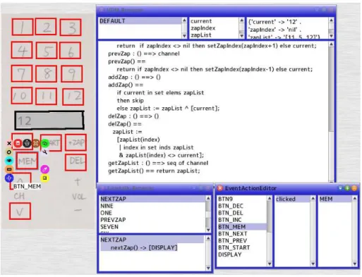
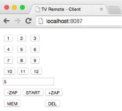
Figure 1 is a screenshot of a UI prototype on Lively Walk-Through. The UI proto-type was constructed by the following steps:
– Wrote the VDM specification shown in Section 3.
– Drew a UI sketch on a paper, took a photo of it, and placed the image on Lively Walk-Through.
Fig. 1.UI prototyping for a TV remote controller with zapping support
NEXTZAP
nextZap() -> [DISPLAY]
Fig. 3.Discussion between UI designer and VDM engineer
– Placed sensor rectangles (the red boxes in Figure 1) on the buttons drawn.
– Wrote actions for buttons in LiveTalk scripts (see Figure 2).
– Associatedclickevent of each button to an action.
LiveTalk is a Domain Specific Language (DSL) that bridges VDM animation and UI widgets. Figure 2 shows the definition of the action of the “next zap” button. The first line is the name of the script. The second line states that the return value of the operation call “nextZap()” is passed to theDISPLAYwidget. TheDISPLAYwidget will show the resulting channel. Other buttons have their actions defined in LiveTalk.
Actions defined in LiveTalk are associated with GUI’s events. When a button is clicked, the button triggers aclickedevent. The system then executes actions associ-ated with the event. Events can be concurrently triggered, but the execution of VDM-SL operations are mutualy excluded and thus serialized by a semaphore.
Figure 3 illustrates a discussion using Lively Walk-Through. After a series of walk-through’s, the UI designer points out that the zap mode is exposed to the user which leads to a confusing interaction. The UI designer also claims that the user does not need theprevZap()operation, but thestartZap()andnextZap()should be unified into one operation for simplicity. The VDM engineer agrees and put it into theTODO
field.
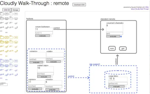
Fig. 4.Diagram with Animation on Cloudly Walk-Through shared on the web
5
Cloudly Walk-Through: Animation for Non-Engineering
Stakeholders
Cloudly Walk-Through is a general diagrams editor with VDM-SL animation capabil-ities. The basic idea behind Cloudly Walk-Through is to explain formal specifications by supplementing them with two kinds of visual notations; diagrams and visual repre-sentation of VDM-SL values.
Some stakeholders without software engineering backgrounds, such as user repre-sentatives and marketing reprerepre-sentatives, often have domain knowledge crucial to pro-duce software systems that fit the application domain. Diagrams and natural language texts are often used to explain architectural designs and important design decisions to such non-engineering stakeholders. Those informal notations have advantages of less technical demands at the cost of semantic ambiguity and uncertain implications. The goal of Cloudly Walk-Through is to take advantages of both the easy-to-understand diagrams and the rigorous formal specification.
Figure 4 is a screenshot of Cloudly Walk-Through animating the remote controller with the zapping support introduced in Section 3. Gray rounded rectangles represent physical components (buttons and a controller module) of a conventional remote troller. Blue dotted rectangles are extension components (zap buttons and zap con-troller) for the zapping support. Small assemblies in rectangles are mini-evaluators. A VDM engineer enters a VDM expression and Cloudly Walk-Through evaluates it when the button below is pressed. The result value is rendered above in a visual repre-sentation with a larger font. The visual reprerepre-sentation lowers the technical barrier for non-engineering stakeholders to comprehend VDM-SL’s expressions.
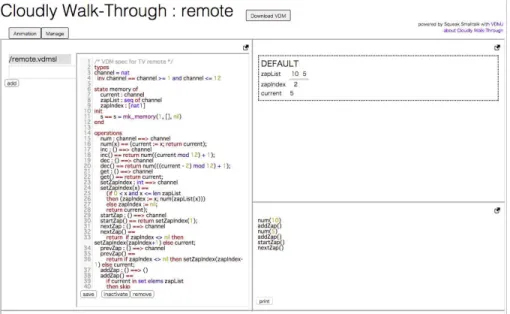
Fig. 5.VDM-SL IDE of the Cloudly Walk-Through
The animation is shared on the web. Cloudly Walk-Through manages registered users’ permissions to watch or manage each animation instance. Any registered user who as the permission to watch the animation can see the on-going animation by open-ing the URL of the animation instance.
Figure 5 shows the VDM-SL IDE on Cloudly Walk-Through for formal specifica-tion enginneers. Formal engineering users can manage the source tree of the VDM-SL specification on the left side of the IDE. The right-top area displays the state of the on-going animation. Diagram representation of VDMPad [15] is used to render the value of each state variable. Values are grouped by dashed rectangles using modules. The top right area is a text editor called a Workspace, where the user can write and evalu-ate VDM expressions. Those components are similar to their counterparts in VDMPad. The difference is that the specification is stored in a source file tree on the server, and the animation state is shared by all users. In addition, Cloudly Walk-Through has a git interface to manage the source tree by git to push, pull, commit, revert and view log and status. Formal engineers can synchronize source trees with git repository to use Cloudly Walk-Through in conjunction with other formal methods tools such as the Overture tool and VDMTools. Users can also download a zip archive of the source tree by pressing a “Download ZIP” button.
6
Webly Walk-Through: Animation for Client Programs
Webly Walk-Through is a prototype Web API server where client programs can be used as an alternative until the implementation of Web API server will be completed.
Rapid development is often critical to web application services. A web API is the interface that separates the server side from the client side. The server and the client are sometimes developed by different teams in parallel. The specification of a web API is the key to successful development of web applications. Rigorous specifications can help the development of the client side as well as the server side. In conventional devel-opment, the client team typically implements stubs to test their program code and the user interface design. Webly Walk-Through serves as a Web API server by animating a VDM-SL specification of the web API. Webly Walk-Through uses JSON to transfer data between the web API server and its clients. JSON is a widely used open standard format and encoders and decoders are available in many programming languages.
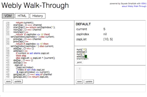
Fig. 6.VDM IDE on Webly Walk-Through
Webly Walk-Through provides three kinds of web services: (1) Web IDE for VDM-SL and web contents, (2) Web API, and (3) files with static contents. Figure 6 is a screenshot of the Web IDE. The Web IDE has three tabs; VDM, HTML and History. In the VDM tab, formal engineers can write a VDM-SL specification of the Web API. The state of the on-going animation is shown in the right-top area. The right-middle is a Workspace that can be used to evaluate arbitrary VDM expressions. Translation rules between VDM values and the corresponding JSON data are defined in the right-bottom area. In this particular example, channel numbers are the only data transfered between the server and clients, and no translation rule is needed.
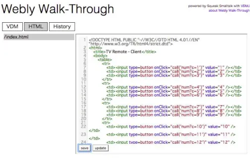
Webly Walk-Through also provides support for files with static contents. The HTML tab provides a web-based static content editor to manage and modify the files. Figure 7 is a screenshot of the static content editor.
Fig. 7.File Editor on Webly Walk-Through
The Web API service is driven by VDM-SL animation. A Webly Walk-Through server publishes operations and functions at URLs
http://<hostname>:<port>/<module name>/<operation/function name>for a modularized specification, or
http://<hostname>:<port>/<operation/function name>for a flat spec-ification. The API call may be requested as a Get method with a query part or post method with the form-data format. When the server receives an API call with param-eters, each parameter in a JSON format is translated into a VDM value according to user-defined translation patterns. The server then evaluates the operation or function call with the translated arguments. The resulting value is translated into a JSON format and sent to the client program. Figure 8 is a screenshot of a web browser dispatching an API. The argument to thenumoperation is5, which is identical both in JSON and VDM-SL. The operationnum(5)is then evaluated and the return value5is sent back to the web browser in JSON format, which is again identical to its VDM-SL counter-part.
Fig. 9.The client UI that uses the Web API animated by Webly Walk-Through
The Webly Walk-Through server provides web pages with static contents such as html, css and javascript files. Figure 9 shows a screenshot of the UI page for the remote
controller. The page has a JavaScript code that invokes Web API’s in the specification, such as num, startZap, nextZap and so on.
The API calls received by the server are recorded along with translated arguments and return values into the history page shown in Figure 10. VDM expressions evaluated in the IDE page are also recorded.
Fig. 10.Webly Walk-Through IDE shows the access log on the server with states and expressions of the VDM spec
7
Related Work
VDMPad [14, 15] is a simple Web IDE for VDM-SL. VDMPad was designed to be lightweight authoring environment for VDM-SL engineers at the earlier stages of the specification phase. The user writes, tests and debugs a specification by animating the specification. Lively Walk-Through, Cloudly Walk-Through and Webly Walk-Through are implemented based on VDMPad. Although the three Walk-Through systems pro-vide specification editors, the systems put more values on the animation part.
PVSio-web [16] is a UI prototyping tool to animate executable formal specification generated from a graphical diagram notation called Emucharts. A VDM-SL generator from Emucharts was recently developed [9]. PVSio-web aims at development of safety-critical systems, such as medical devices, with precise UI design. Lively Walk-Through assumes more sketchy UI prototypes at the earlier stages of the development. PVSio-web, Lively Walk-Through and Cloudly Walk-Through share a common objective, that is, to engage stakeholders other than formal engineers with lightweight formal methods. BMotion Studio [6] is a graphical animation builder aiming at communications be-tween developers and domain experts. It enables to build a graphical representation using labels, images and buttons that drives an Event-B specification.
The Remote Control Interface of VDMJ enables Java program to control models in VDM [12]. The resulting GUI can be used by non-engineering stakeholders. The Java code needs to be written by engineers who understand both VDM and Java. Overture VDMPP GUI automatically generates a simple UI to display state variables and push buttons that invoke operations and functions without any GUI programming effort.
The Crescendo tool [3] is a co-simulation environment that bridges between phys-ical model simulations and executable formal specifications written in VDM-RT. The Crescendo tool has 3D animator of Continuous-Time simulation model. The users of the Crescendo tool can be considered multidisciplinary in the sense that Continuous-Time models are based on physical systems including differential equations while Discrete-Event models are typically of computer domain expressed in VDM.
DisCo [13] is a simulator that combines a logical event level in formal specification and graphical animation for agile development of games.
8
Discussion
Formal specifications serve as reliable references in the lightweight use of formal meth-ods. Formal specifications can be a strong tool to organise domain knowledge from do-main experts. Animation has a potential to enable collaboration for a diversity of stake-holders who participate in development and use of formal specification when combined with visualisations and programming languages. Figure 11 illustrates the relations be-tween the different kinds of animation systems and expertise in software development.
VDMJ Smalltalk
SOMETHINGit
customers and users
VDM animation
UI/UX design
UI designers
domain analysis
specification
VDM Engineers Exploratory Spec
on VDMPad client
programs
UI sketch on Lively WT
Web API on Webly WT
web application
Diagrams with animations
on Cloudly WT
Animation with a graphical presentation is the key to having non-engineering stake-holders participating in the development and use of formal specification. Lively Walk-Through combines executable specifications with UI designs. UI designers may not have formal engineering skills, but can interact with executable formal specifications through animated UI prototypes. Cloudly Walk-Through visualises execution of spec-ifications to have domain experts review formal specspec-ifications. Domain experts in this context typically do not have formal engineering skills. Graphical presentations used in the animation systems include casual diagrams, domain-specific diagrams, sketchy UI designs and precise UI prototypes. One possible direction for future work is a col-laboration with massive data visualisation/analysis techniques such as plots, graphs, geometries and volume data.
An interface with programming languages is the key to expanding use of specifi-cation animation to wider scenes of systems development. Webly Walk-Through com-bines formal specifications with implementation code in order to build rapid prototypes. SOMETHINGit, a foundation library of Lively Walk-Through, provides ability to eval-uate VDM expression as a part of Smalltalk programs. These systems assume that users have engineering skills and their tasks are thus more useful for software engineers. One possible future work direction is to embed a formal specification and its interpreter into runtime code so that the system can be debugged referring to the specification with regard to the suspicious execution context at hand.
9
Concluding Remarks
In this paper, three animation systems, Lively Walk-Through, Cloudly Walk-Through and Webly Walk-Through have been introduced as tools to extend the reach of formal specification towards stakeholders other than formal engineers. They are all derived from the sources of VDMPad but have different objectives and target users. As systems development requires cross-disciplinary collaborations, a media for communication be-tween formal engineers and other stakeholders is needed. The three systems are our attempt to design such communication media using animation mechanism of VDM-SL.
The three systems have not yet been used in practical developments. However, we hope to have opportunities to apply them in industrial projects in the future. We also plan to elaborate further on usage of animation in additional phases of software development.
Acknowledgments This work is supported by Grant-in-Aid for Scientific Research (S) 24220001.
References
1. Barnes, J., Chapman, R., Johnson, R., Widmaier, J., Cooper, D., Everett, B.: Engineering the Tokeneer Enclave Protection Software. In: Proceedings of the 1st IEEE International Symposium on Secure Software Engineering (ISSSE’06). IEEE (March 2006)
2. Fitzgerald, J., Larsen, P.G., Sahara, S.: VDMTools: Advances in Support for Formal Model-ing in VDM. ACM Sigplan Notices 43(2), 3–11 (February 2008)
3. Fitzgerald, J., Larsen, P.G., Verhoef, M. (eds.): Collaborative Design for Embedded Systems – Co-modelling and Co-simulation. Springer (2014), http://link.springer.com/book/10.1007/978-3-642-54118-6
4. Gilliam, D., Powell, J., Bishop, M.: Application of Lightweight Formal Methods to Software Security. In: Proceedings of the 14th IEEE International Workshops on Enabling Technolo-gies: Infrastructure for Collaborative Enterprise (WETICE’05). IEEE (2005)
5. Kurita, T., Nakatsugawa, Y.: The Application of VDM++ to the Development of Firmware for a Smart Card IC Chip. Intl. Journal of Software and Informatics 3(2-3), 343–355 (October 2009)
6. Ladenberger, L., Bendisposto, J., Leuschel, M.: Visualising Event-B Models with B-Motion Studio. In: Proceedings of the 14th International Workshop on Formal Methods for Industrial Critical Systems. pp. 202–204. Springer-Verlag (November 2009)
7. Larsen, P.G., Battle, N., Ferreira, M., Fitzgerald, J., Lausdahl, K., Verhoef, M.: The Overture Initiative – Integrating Tools for VDM. SIGSOFT Softw. Eng. Notes 35(1), 1–6 (January 2010), http://doi.acm.org/10.1145/1668862.1668864
8. Lausdahl, K., Larsen, P.G., Battle, N.: A Deterministic Interpreter Simulating A Distributed real time system using VDM. In: Qin, S., Qiu, Z. (eds.) Proceedings of the 13th interna-tional conference on Formal methods and software engineering. Lecture Notes in Com-puter Science, vol. 6991, pp. 179–194. Springer-Verlag, Berlin, Heidelberg (October 2011), http://dl.acm.org/citation.cfm?id=2075089.2075107, ISBN 978-3-642-24558-9
9. Masci, P., Couto, L.D., Larsen, P.G., Curzon, P.: Integrating the PVSio-web modelling and prototyping environment with Overture. In: Ishikawa, F., Larsen, P.G. (eds.) Submitted to the 13th Overture Workshop. Oslo, Norway (June 2015)
10. Nakakoji, K., Yamamoto, Y.: chap. Conjectures on How Designers Interact with Represen-tations in the Early Stages of Software Design. Chapman & Hall (2013)
11. Nielsen, C.B.: Dynamic Reconfiguration of Distributed Systems in VDM-RT. Master’s the-sis, Aarhus University (December 2010)
12. Nielsen, C.B., Lausdahl, K., Larsen, P.G.: Combining VDM with Executable Code. In: Derrick, J., Fitzgerald, J., Gnesi, S., Khurshid, S., Leuschel, M., Reeves, S., Ric-cobene, E. (eds.) Abstract State Machines, Alloy, B, VDM, and Z. Lecture Notes in Computer Science, vol. 7316, pp. 266–279. Springer-Verlag, Berlin, Heidelberg (2012), http://dx.doi.org/10.1007/978-3-642-30885-7 19, ISBN 978-3-642-30884-0
13. Nummenmaa, T., Tiensuu, A., Berki, E., Mikkonen, T., Kuittinen, J., Kultima, A.: Supporting agile development by facilitating natural user interaction with exe-cutable formal specifications. SIGSOFT Softw. Eng. Notes 36(4), 1–10 (Aug 2011), http://doi.acm.org/10.1145/1988997.2003643
14. Oda, T., Araki, K.: Overview of VDMPad: An Interactive Tool for Formal Specification with VDM. In: International Conference on Advanced Software Engineering and Informa-tion Systems (ICASEIS) 2013 (Nov 2013)
15. Oda, T., Araki, K., Larsen, P.G.: VDMPad: a Lightweight IDE for Exploratory VDM-SL Specification. In: Plat, N., Gnesi, S. (eds.) FormliSE 2015. In connection with ICSE 2015, Florence (May 2015)
16. Oladimeji, P., Masci, P., Curzon, P., Thimbleby, H.: PVSio-web: a tool for rapid prototyp-ing device user interfaces in PVS. In: FMIS2013, 5th International Workshop on Formal Methods for Interactive Systems, London, UK, June 24, 2013 (2013)
17. Ubayashi, N., Nakajima, S., Hirayama, M.: Context-dependent product line engineering with lightweight formal approaches. Science of Computer Programming (2012)
18. Woodcock, J., Larsen, P.G., Bicarregui, J., Fitzgerald, J.: Formal Methods: Practice and Ex-perience. ACM Computing Surveys 41(4), 1–36 (October 2009)
Integrating the PVSio-web modelling and prototyping
environment with Overture
Paolo Masci1, ⋆
, Luis Diogo Couto2, Peter Gorm Larsen2, and Paul Curzon1 1 School of Electronic Engineering and Computer Science
Queen Mary University of London, United Kingdom {p.m.masci,p.curzon}@qmul.ac.uk
2 Department of Engineering
Aarhus University, Denmark {ldc,pgl}@eng.au.dk
Abstract. Tools are needed that overcome the barriers preventing development teams using formal verification technologies. We present our work integrating PVSio-web with the Overture development and analysis environment for VDM. PVSio-web is a graphical environment for modelling and prototyping interactive systems. Prototypes developed within PVSio-web can closely resemble the vi-sual appearance and behaviour of a real system. The behaviour of the prototypes is entirely driven by executable formal models. These formal models can be gen-erated automatically from Emucharts, graphical diagrams based on the Statechart notation. Emucharts conveniently hides aspects of the formal syntax that create barriers for developers and domain experts who are new to formal methods. Here, we present the implementation of a VDM-SL model generator for Emucharts. An example is presented based on a medical device. It demonstrates the bene-fits of using Emucharts to develop a formal model, how PVSio-web can be used to perform lightweight formal analysis, and how the developed VDM-SL model generator can be used to produce a model that can be further analysed within Overture.
Keywords: Prototyping, VDM-SL, PVSio-web.
1
Introduction
Formal verification technologies can help developers to discover design problems early in the development process of safety critical systems. These technologies, however, usually require significant mathematical sophistication, and many developers perceive this as a barrier that overweighs the advantages of using such tools.
PVSio-web [1,2] is a new research tool developed to ease the use of formal methods technologies when developing safety-criticalinteractivesystems, i.e., ones that involve interaction between devices and human users. It provides a graphical environment that allows developers to rapidly generate interactive prototypes resembling the visual ap-pearance and behaviour of the real system (see Figure1). Underneath the interface, the